|
LeCroy LA354 500 Mhz+ Color Analog Oscilloscope
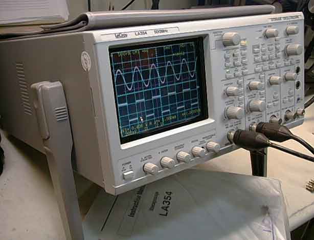
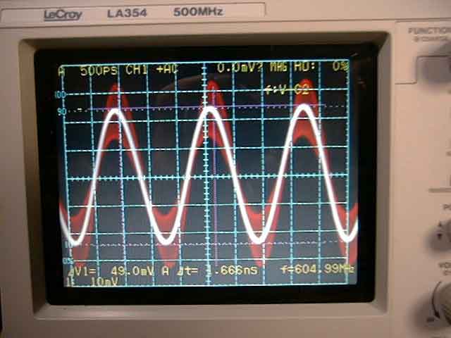
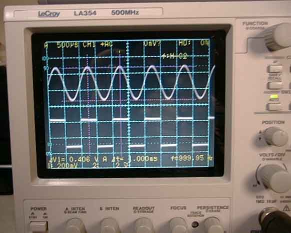
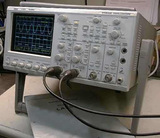
The LA-354 is a 4 channel color LCD display, analog storage oscilloscope. This High-end analog oscilloscope for the digital age has a conservatively rated 500Mhz band width. In the photos below the scope is shown displaying a 1 KHz, 600Mhz and "YES" - it will trigger to around 900mhz with some attenuation. This scope has variable persistence in a choice of colors which is exceptional for glitch capture and single event viewing. It has a full set range of cursor measurements and built in frequency counter.
Displaying a 600 Mhz Signal Showing Persistence from a 40% AM Modulation Burst
Look below for more detailed information or visit LeCroy's Web Site. Look around, they have a number of interesting pages relating to features and set up with this scope. Full service for this scope can be obtained through LeCroy. Displaying 1 Khz Signal
This scope is in mint condition and performs flawlessly. Whether or not you are looking for a great general scope or specifically an analog scope to compliment the digital scopes in you lab, the LeCroy LA354 is the perfect choice.
LeCroy LA-354 -
Specifications
|
||||||||||||||||||||||||||||||||||||||||||||||||||||||||||||||||||||||||||||||||||||||||||||||||||||||||||||||||||||||||||||||||||||||||||||
| Display | |
|
5.5-inch rectangular Color LCD TFT (240V x 320H dots) with variable persistence, electronic graticule (8 x 10 div). |
|
Scan Converter Tube: 2 Inch diameter SCT; CCD: approximately 450 x 700 pixel CCD with video RAM. SCT and CCD connected via Optical Fiber Bundle. |
|
Rear panel BNC 75 Ohm connection: NTSC Color Composite. |
| Vertical Deflection System | |
|
CH1, CH2, CH3, CH4, ADD (CH1+CH2), ALT, CHOP |
| Channel 1, 2 Sensitivity | 2 m/Vdiv - 5 V/div +2%, 11 step (1-2-5) |
| Fine Adjuster | 2 mV/div ~ 12.5 V/div continuously variable in 1% display scale increments |
| Frequency bandwidth | DC ~ 500 MHz
(2mV/div ~ 5 V/div) DC ~ 20 MHz or, DC ~ 100 MHz selectable limiting |
| VSWR | Less than 1.35 through DC ~ 500 MHz (with 50 Ohm input) |
| Rise time | Approx. 700 ps @ 20 mV/div (freq. bandwidth x rise time = 0.35) |
| Input coupling | AC, DC, GND |
| Input RC | 1M ohm input: 1M Ohm +1.5%//16 pF +2pF, 50 ohm input: 50 ohm +1% |
| Maximum input voltage | 1 M ohm input: +400 V max. 50 ohm input: 5 V RMS |
| Polarity switching | CH2 only |
| Probe sensors | 1:1, 1:10, 1:100 detection possible |
| Offset voltage variable range | Offset voltage /
Vertical axis range +1 V / 2mV/div ~ 50 mV/div +10 V / 0.1 V/div ~ 0.5 V/div +100 V / 1 V/div ~ 5 V/div |
| Channel 3, 4 Sensitivity | 100mV, 500mV/div |
| Accuracy | +3% (+10°C ~ +35°C) |
| Frequency Bandwidth | DC ~ 500 MHz |
| Rise time | Approx. 700 ps (freq. bandwidth x rise time = 0.35) |
| Input coupling | AC, DC |
| Input RC | Direct: 1 M ohm + 1.5%//16 pF+3pF |
| Maximum input voltage | +400 V max. |
| Probe readout auto-sensor | 1:1, 1:10, 1:100 detection possible |
| Triggering | |
| A triggering | |
| Sources | CH1, CH2, CH3, CH 4, LINE |
| Coupling | AC, DC, HF-REJ, LF-REJ |
| Polarity | +/- |
| TV sync | |
| Line selection | NTSC:1 ~ 525H; PAL (SECAM):1 ~ 625H; HDTV:1 ~ 1125H |
| B & B' triggering | |
| Sources | CH1, CH2, CH3, CH4 |
| Coupling | AC, DC, HF-REJ, LF-REJ |
| Polarity | +/- |
| Event Delay | |
| Count | Setting range:1 ~ 65,535; maximum count freq.: 50MHz |
| Burst | Time setting range: 0.15 microsec ~ 9.99sec |
| Auto setup | Input channels: CH1, CH2, Freq. range: 50 Hz ~ 100 MHz |
| Horizontal deflection system | |
| HORIZONTAL DISPLAY | A, ALT, B, B', B & B', X-Y, AUTO, NORM, SINGLE |
| A sweep | |
| Mode | AUTO, NORM, SINGLE |
| Sweep time | 5 ns/div ~ 500 ms/div +2% 25-step (1-2-5) Fastest sweep time: 500 ps/div Fine adjuster: 5 ns/div ~ 1.5 s/div Calibrated Variable |
| B & B' sweeps | |
| Dual Delays | Triggered DUAL
delays: CH1, CH2, CH3, CH4 Continuous DUAL delays: RUNS AFTER |
| Sweep time | 5ns/div ~ 20 ms/div +2%, 21 step (1,2,5) |
| Delay time range | 0.2 div ~ 10.2 div; : +[(setting value x 0.005) +(sweeptime x 0.1)] -55 ns |
| Magnifier (MAG) | 10 times; Accuracy: +5% (+10°C ~ +35°C) |
| X-Y Operation: DC-10MHz | X axis: CH1,
Accuracy: +2% (+10°C ~ +35°C) Y axis: CH1, CH2, CH3, CH4, ADD |
| CH2 OUT | |
| Output voltage | 20 mV/div +30% |
| Frequency output range | DC ~ 200 MHz (50 ohm load) |
| Output resistance | 50 ohm +20% |
| External
Intensity Modulation (Z axis) |
Minimum modulation
voltage: 0.5Vp-p Polarity: Positive (dark)/negative (bright) Frequency range: DC ~ 5 MHz Input withstand voltage: 40V |
| Video OUT | NTSC Composite, 480 lines (V) x 640(H), 1Vp-p +/-0.3V, 75 Ohm BNC |
| Calibrator | Waveform: Square Repetitive frequency: 1 kHz Accuracy: +0.1% Output voltage: 0.6V Accuracy: +1% |
| Active Probe Power supply | Voltage: +12 V, 2 FET probes connectable, offset control possible |
| Frequency Counter | Display digits: 5
digits shown at all times (6 Digits available, Option #3) Accuracy: +0.01% Frequency measurement range: 2Hz ~ 500 MHz |
| Cursor measurement | Voltage axis: 2 Time axis: 2 Time difference: Delta t Voltage difference: Delta V Delta t & Delta V can be simultaneously displayed |
| Save/recall function | Number of setups:
256 max. Comments: 12 characters / title. |
| Power Supply | Voltage range: AC
100 V ~ 240 V Frequency range: 50Hz, 60Hz Power consumption: 120 VA max. |
| Dimensions and weight | Approx. 320W x 160H x 420L mm/approx. 8.5 kg |
| Accessories | (1) Power cable, (1) LA-354 Operation Manual, (1) Accessory Pouch |
Warranty
As our many customers will attest, we will do our very best to resolve any customer problems. But our official policy is:
- All items sold carry a 3-day Right Of Return Warranty.
- All claims must be made within 3 days of receipt.
- All warranties are void if the calibration / warranty seals are broken.


